Sunday, September 30, 2012
Wromp
We've decided the main sensor that we are going to be using is an LED matrix and a microphone.
Realistically… How would we get the camera LEDs to work with the kaleidoscope, we still want our project to be where you are turning a part of you into the LEDs, but instead of it literally being an image of you it will show you a visual representation of your voice into an LED visualizer!
We still want to create an immersive experience but perhaps instead of being just an individual experience it could be a small group experience. I was thinking that we would represent the tones or pitches of a voice through the colors of the LEDs. Possibly having either a loud tone or high pitched noise displaying energetic colors such as yellows, oranges and reds. A soft voice or a low pitch would yield you violet or purple colors.
Would the thing be going off if people were talking on the other side of the room? We want to make it where it would be more direct, as if you had to talk into the thing. I still don't know what to call it yet. The working title is the 'Sound Activated Visionoscope'.
This could open a new door though because how would a viewer know to walk up and start talking into the... thing?
Here we got the LED matrix working with two potentiometers making the LED display kind of like an etch-a-sketch
http://www.youtube.com/watch?v=SsNJ-xU4W9o
project links:
http://arduino.cc/en/Tutorial/RowColumnScanning
another one that we did:
http://www.youtube.com/watch?v=aJ3978xWSuo
project links: http://arduino.cc/playground/Main/DirectDriveLEDMatrix

Affordances: Discussion Questions for Class on Monday
"an action possibility available in the environment to an individual, independent of the individual's ability to perceive this possibility"
How do you understand this definition/description of affordance? Please put into your own words. What if anything may or may not be problematic about this interpretation of the notion of affordances?
Get into your groups and answer the following questions
Pick three aspects/environmental conditions of this room or the third floor of FAC. Describe each of these aspects as an affordance. What activity is implied by the material? What sorts of sensory input does this condition/object offer the user? One way of doing this might be able to put yourself in the place of an alien. What about the object or condition compels you to act upon it in a particular way?
What do you think is the difference between usefulness and utility with respect to affordances?
What might be a false affordance? Create a situation other than that of the cat on the glass floor who is afraid to walk because the glass is transparent and there is a drop in floor? Think about how zoos keep animals in w/o cages or slapstick comedy.
Are we aware of all of the affordances of an object or a condition? Do you think affordances are cultural? Are they different for people with disabilities?
Draw parallels between the idea of affordances and intentionality and art. What is the relationship between metaphor and affordances? I think this might be worth thinking about this.
Friday, September 28, 2012
Thursday, September 27, 2012
project 38


chapter 3 project 9


Wednesday, September 26, 2012
Brainstorming!
We want to create an immersive, individual experience in which you give something (your image) and in return you receive feedback of your own image in the form of led lights. The image is distorted by the simplification of the LEDs and the reflections of the mirrors. There is little to no integrity to your actual image, the device is just using your image as a base to create fractal patterns.
The "kaleidoscope" aspect is just a device for distortion. I was also thinking what if we had a camera that took a still frame instead of video so it has more of a context of being forever captured? If you're seeing your image distorted, is that unsettling somehow? It can be but at the same time you can't take your eyes off of it.
It reminds me of doing the photo booth pictures on my Mac or the popular "Face Swap" meme.
Since there may be little to no integrity in the visual representation of your image being reflected, is it still an image of you? Where is the line drawn where it stops being an image of you and just starts being an array of pixels. How much can you distort an image before it is no longer that original image? When does it stop being "you"? Is it when you can't recognize yourself anymore in the image? The image is always formed from the data of your undistorted image.
This video demonstrates how we are going to use the webcam and an LED matrix to display the image.
http://www.youtube.com/watch?v=vERS_CKG2iQ
We found a few guides to RGB LED matrix
http://www.ladyada.net/products/rgbledmatrix/
http://arduino.cc/forum/index.php?topic=51656.0
But this was disheartening, they said in order to do a 32x32 RGB LED matrix you would need 16 arduino boards each powering 1, 8x8 RGB LED matrix.
If we aren't able to do the RGB matrix, we think that just a 2 color threshold display of your image will be just as effective visually and will still stay true to our concept.
Tuesday, September 25, 2012
Erin | Ch4 Prj 11, 12, 13
Prj 11 Piezo Sounder Alarm
This version sounds like a creaky door.
// Project 11 - Piezo Sounder Alarm
float sinVal; //holds sin value to cause the tone to rise and fall
int toneVal;  //takes the sin val and converts to frequency

void setup() {
  pinMode(8, OUTPUT);
}

void loop() {
        for (int x=0; x<180; x++) { //set up so sine value doesn't go into negative

        // convert degrees to radians then obtain sin value
        sinVal = (sin(x*(3.1412/180)));
        // generate a frequency from the sin value
        toneVal = 50+(int(sinVal*100));
        tone(8, toneVal);
        delay(25); //defined here to allow for sufficent delay
}
}
Prj 12 Piezo Sounder Melody Player
with commentst
// Project 12 - Piezo Sounder Melody Player
#define NOTE_C3  131 //these define directives define notes with specific tones C3 through B4
#define NOTE_CS3 139
#define NOTE_D3  147
#define NOTE_DS3 156
#define NOTE_E3  165
#define NOTE_F3  175
#define NOTE_FS3 185
#define NOTE_G3  196
#define NOTE_GS3 208
#define NOTE_A3  220
#define NOTE_AS3 233
#define NOTE_B3  247
#define NOTE_C4  262
#define NOTE_CS4 277
#define NOTE_D4  294
#define NOTE_DS4 311
#define NOTE_E4  330
#define NOTE_F4  349
#define NOTE_FS4 370
#define NOTE_G4  392
#define NOTE_GS4 415
#define NOTE_A4  440
#define NOTE_AS4 466
#define NOTE_B4  494

#define WHOLE 1 //these define note lengths
#define HALF 0.5
#define QUARTER 0.25
#define EIGHTH 0.125
#define SIXTEENTH 0.0625

// make integer array for Puff the magic dragon

int tune[] = { NOTE_C4, NOTE_C4, NOTE_C4, NOTE_C4, NOTE_C4, NOTE_B3, NOTE_G3, NOTE_A3,
NOTE_C4, NOTE_C4, NOTE_G3, NOTE_G3, NOTE_F3, NOTE_F3, NOTE_G3, NOTE_F3, NOTE_E3, NOTE_G3,
NOTE_C4, NOTE_C4, NOTE_C4, NOTE_C4, NOTE_A3, NOTE_B3, NOTE_C4, NOTE_D4};

// integer array to assign the length of the note as it is played
float duration[] = { EIGHTH, QUARTER+EIGHTH, SIXTEENTH, QUARTER, QUARTER, HALF, HALF,
HALF, QUARTER, QUARTER, HALF+QUARTER, QUARTER, QUARTER, QUARTER, QUARTER+EIGHTH, EIGHTH,
QUARTER, QUARTER, QUARTER, EIGHTH, EIGHTH, QUARTER, QUARTER, QUARTER, QUARTER,
HALF+QUARTER};

int length; // used to calculate and store the lenth of the array (number of notes in the tune)

void setup() {
        pinMode(8, OUTPUT);  // digtial pin 8 to output to piezo
length = sizeof(tune) / sizeof(tune[0]);  // initialize the integer with the number of notes using the sizeof() function
//which returns the number of bytes in the parameter (two bytes on arduino)  tunes[] has 26 notes
// they are divided number of bytes in this case 26/2 = 13, if the tune is replaced this is recalculated
}

void loop() {
        for (int x=0; x<length; x++) { //counts the nnumber of timest there are notes inthe melody
        tone(8, tune[x]); //play the tune
        delay(1500 * duration[x]);  //then wait for the time ot let it play -can speed up or slow down here
        noTone(8); //turn off the tone
}
delay(5000); // stop for 5 seconds before beginning again
}
Ch4 Project 13 Piezo Knock Sensor
This is not quite working as it should, though admittedly alligator clips would be ideal. I've bent my connectors. The sensitivity had to be adjusted for it to even work, I can knock the table and the LED turns on, but sometimes the led turns on even when my hand hovers above it.
// Project 13 - Piezo Knock Sensor
//is this what touch lamps use?
int ledPin = 9; // LED on Digital Pin 9
int piezoPin = 5; // Piezo on Analog Pin 5
int threshold = 60; // The sensor value to reach before activation
int sensorValue = 0;  // A variable to store the value read from the sensor
float ledValue = 0; // The brightness of the LED


void setup() {
        pinMode(ledPin, OUTPUT); // Set the ledPin to an OUTPUT
        // Flash the LED twice to show the program has started
        digitalWrite(ledPin, HIGH); delay(150); digitalWrite(ledPin, LOW); delay(150);
        digitalWrite(ledPin, HIGH); delay(150); digitalWrite(ledPin, LOW); delay(150);
}

void loop() {
        sensorValue = analogRead(piezoPin);  // Read the value from the sensor
        if (sensorValue >= threshold) { // If knock detected set brightness to max
        ledValue = 255;
}
analogWrite(ledPin, int(ledValue) ); // Write brightness value to LED
ledValue = ledValue - 0.05; // Dim the LED slowly
if (ledValue <= 0) { ledValue = 0;}  // Make sure value does not go below zero
}
project 14 Light Sensor done in class
Heart Beat Representation is finally WORKING!
WE GOT IT WORKING!
Its a very exciting moment.
Julia and I have been trying to apply the variables for heart beat (that was prewritten in the example codes) to work with a simple image, and after battling with Processing and Arduino for what seemed like a lifetime, we finally got an ellipse to beat.
May not seem like much, but when you put the sensor on your finger tip and hold it tightly enough that you can actually feel the pulse in said finger, you'll realize its perfectly in sync with the beating circle...give or take.
The first success was too slow, so we sped it up for the second video which was amazingly accurate in the participant keeps sharp movements to a minimal. (Shaking the sensor gets it to lose the beat because the pulse sensor is programmed to look for a rhythm so as to keep out subtle movements as a "heartbeat." Due to this, too much motion tells the arduino that its not a heart beat-which is a good thing or it would be picking up your breathing more than a heart beat.
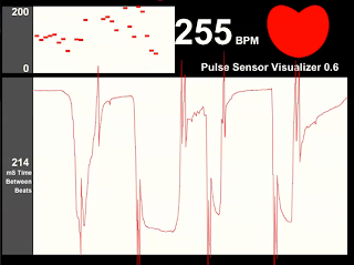
And then came the problems...
So we've been troubleshooting. Try as we might to get our sensor to give us strong, steady heart rate readings, its keeps having random spats of sporadic beats. (Because I doubt our heart rates just went from 78 to 659 beats per minute.)
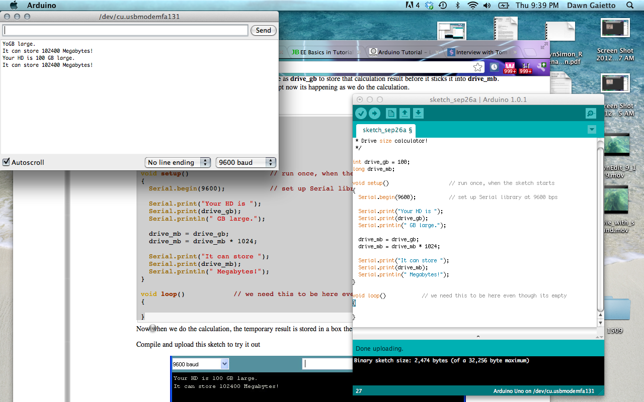
So I looked at the serial monitor for arduino and discovered something.
It seems to work fine in arduino, as seen above. But as soon as I boot up processing, you can see what happens below:
So I looked at the serial monitor for arduino and discovered something.
It seems to work fine in arduino, as seen above. But as soon as I boot up processing, you can see what happens below:
And then randomly sometimes the visualization at least APPEARS to be steady...appears being the key word in that sentence.
Monday, September 24, 2012
midterm project
my midterm project is going to consist of using an arduino and a temperature/humidity sensor to control a digital camera. the camera will take a shot each time that the humidity and/or temperature vary a predetermined amount. the idea is to take a serial view at a single landscape and notate the subtle variations that occur visually as the environmental conditions vary.
the links below are information I have compiled in my search for hacking a camera and types/codes for the humidity sensor:
https://www.sparkfun.com/products/8227
http://arduino.cc/forum/index.php/topic,18610.0.html
http://www.instructables.com/id/Hacking-A-Keychain-Digital-Camera-for-Arduino-Cont/
http://www.zipfelmaus.com/blog/hack-a-canon-camera-and-controll-it-with-an-arduino/
http://arduino.cc/blog/category/images/camera/


PWN on Arduino`s blink sketch
We started varying the delay of the blinking LED on the Arduino to experiment with PULSE WIDTH MODULATION.
Midterm project ideas and process
After talking several times to Gladdys, me and Claudia decided to use a fabric doll as a voodoo doll with bend sensors in order to express our concept and perhaps use it on Installation class next semester.
So, there will be two rooms:
 This is one of the dolls:
This is where we got our inspiration from:
The whole idea with the voodoo doll is to engage the viewer in a sadistic experience and see his reaction; will he like how it feels? Will he notice that it isn`t correct under society`s guidelines?
So, there will be two rooms:
Both of them will be filled with people, with or without the sensors that conects it to the voodoo doll. In both of them, people with sensors will be controlled by people without sensors, in the other room, and vice-versa. They might see each other through camera surveillance, but it`s not certain yet.Here are the sensors we are considering to use both on the players and on the dolls:

This is the diagram we are considering to use as guideline:
Doll -> Arduino -> Player -> Camera ->Player
Midterm Project Process
So Alisyn and I have been thinking a lot about our project especially after the feedback we received when we presented our project proposal.
Now, we're thinking of using a motion sensor connected to the hand via a glove or something more inconspicuous, that would send data to processing which would draw the person wearing the sensors movements as they are speaking and moving their hands. This way movement can be a form of identity. Everyone moves in an unique way. The sensor can way of visualizing this.
Here are some sites about the motion sensor that we've been looking into:
http://www.instructables.com/id/Arduino-Controlled-Motion-Sensor/
http://www.hacktronics.com/Tutorials/arduino-motion-sensor.html
http://keeganmann.wordpress.com/2011/04/15/thingspeak-light-sensor-test/
Also, we may need to look into wireless communication between arduino and processing.
Sunday, September 23, 2012
I hope you don't mind my method of posting fewer but larger posts
Project 8 - RGB Mood Lamp
Album Link: http://imgur.com/a/z07TP#0
Project 9 - LED Fire Effect
Album Link: http://imgur.com/a/td4Ty#0
Video Link: http://youtu.be/SUC8hiGeP1s
Project 10 - Serial Controlled Mood Lamp
Album Link: http://imgur.com/a/tQEbx#0
Video Link: http://youtu.be/N3EDyBnBLTw
Project 11 - Piezo Sounder Alarm
Video Link: http://youtu.be/uJWuUlbyqwo
Project 12 - Piezo Melody Maker
Video Link: http://youtu.be/B-Xl-RPRHWM
Potentiometer
http://youtu.be/SJ9TIWNkZPc
RGB LED
http://youtu.be/TGhJOLkyMAk
This is just some practice I was doing with the RGB LED's. I found a guide on the Instructables website and followed it. You can find the guide here: http://www.instructables.com/id/Arduino-Examples-1-Make-An-RGB-Led-Randomly-Flash/


Wednesday, September 19, 2012
HYE: PROJECT 9, 10, 11, 12, 13
Project 9. exercise 01
Project9. exercise02
PROJECT 9. LED FIRE EFFECT
PROJECT 10.
PROJECT 11.
PROJECT 12.
PROJECT 13.
HYE, ERIN, KATIRIA: group assignment_soldering, potentiometer code

---------------------------------------
// Pontentiometer Arduino Code
int potPin = 0;
void setup()
{
Serial.begin( 9600);
}
void loop ()
{
int val = map ( analogRead(potPin), 0, 1023, 0, 255);
Serial.println( val);
delay(50);
}
--------------------------------------
Chapter 4, Projects 11,12, and 13
Nisa and I worked on these three projects. Here are the videos for each project.
Project 13 - Piezo Knock Sensor -
Project 13 - Piezo Knock Sensor -
Project 11 - Piezo Sounder Alarm -
Project 12 - Piezo Sounder Melody


CH 3 7,8,9,10
Project 7 Pulsating Light
Project 8 Mood Lamp
Project 9 Fire
Project 10 Serial Mood Lamp


Tuesday, September 18, 2012
CH 3 PROJECT 10
Project 10 was fairly simple. We went through the whole project and recorded us putting in the following values into the serial monitor:
Began: R255 G255 B255
R0
G0
B0
R100
R255
G100
G255
B100
B255
B50
R50
G0
R0
B0
We then decided to play around with the code and added some yellow LEDs which we placed at pin 8 and set as "y" or "Y" set up just like the other colors.


Began: R255 G255 B255
R0
G0
B0
R100
R255
G100
G255
B100
B255
B50
R50
G0
R0
B0
We then decided to play around with the code and added some yellow LEDs which we placed at pin 8 and set as "y" or "Y" set up just like the other colors.


Some PulseSensor Practices
Julia and I have been practicing working with the PulseSensor (especially before we proposed an entire project on this sensor) and we were pleasantly surprised at the ease of use we had with it considering the horror stories we've heard about it.
We downloaded the pulsesensor examples for arduino and processing at PulseSensor.com and while the initial readings were not that accurate and very sporadic, we figured out the tighter we held the sensor to a good pulse point and the less movement we had in the area touching the sensor, the easier time we had recording it. Definitely something we need to think about as our project progresses.


We downloaded the pulsesensor examples for arduino and processing at PulseSensor.com and while the initial readings were not that accurate and very sporadic, we figured out the tighter we held the sensor to a good pulse point and the less movement we had in the area touching the sensor, the easier time we had recording it. Definitely something we need to think about as our project progresses.


Monday, September 17, 2012
Ladyada Serial Port Communication
These are the screenshots of Serial Port Communication tutorial on LadyAda.


Subscribe to:
Posts (Atom)