
Monday, December 12, 2016
Week 16 | Final project Update 5/5
Final Documentation:
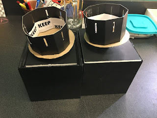
"Keep Moving"
Fritzing Diagram:
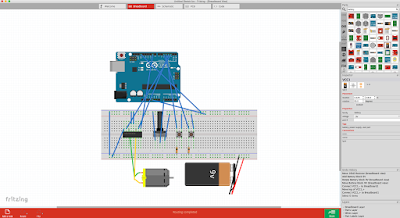
Code used:
const int controlPin1 = 2;
const int controlPin2 = 3;
const int enablePin = 9;
const int directionSwitchPin = 4;
const int onOffSwitchStateSwitchPin = 5;
const int potPin = A0;
int onOffSwitchState = 0;
int previousOnOffSwitchState = 0;
int directionSwitchState = 0;
int previousDirectionSwitchState = 0;
int motorEnabled = 0;
int motorSpeed = 0;
int motorDirection = 1;
void setup(){
pinMode(directionSwitchPin, INPUT);
pinMode(onOffSwitchStateSwitchPin, INPUT);
pinMode(controlPin1, OUTPUT);
pinMode(controlPin2, OUTPUT);
pinMode(enablePin, OUTPUT);
digitalWrite(enablePin, OUTPUT);
}
void loop(){
onOffSwitchState =
digitalRead(onOffSwitchStateSwitchPin);
delay(1);
directionSwitchState =
digitalRead(directionSwitchPin);
motorSpeed = analogRead(potPin)/4;
if(onOffSwitchState != previousOnOffSwitchState){
if(onOffSwitchState == HIGH){
motorEnabled = !motorEnabled;
}
}
if (directionSwitchState !=
previousDirectionSwitchState){
if (directionSwitchState == HIGH){
motorDirection = !motorDirection;
}
}
if (motorDirection == 1){
digitalWrite(controlPin1, HIGH);
digitalWrite(controlPin2, LOW);
}
else {
digitalWrite(controlPin1, LOW);
digitalWrite(controlPin2, HIGH);
}
if (motorEnabled == 1){
analogWrite(enablePin, motorSpeed);
}
else{
analogWrite(enablePin, 0);
}
previousDirectionSwitchState =
directionSwitchState;
previousOnOffSwitchState = onOffSwitchState;
}
"Keep Moving"

Fritzing Diagram:

Code used:
const int controlPin1 = 2;
const int controlPin2 = 3;
const int enablePin = 9;
const int directionSwitchPin = 4;
const int onOffSwitchStateSwitchPin = 5;
const int potPin = A0;
int onOffSwitchState = 0;
int previousOnOffSwitchState = 0;
int directionSwitchState = 0;
int previousDirectionSwitchState = 0;
int motorEnabled = 0;
int motorSpeed = 0;
int motorDirection = 1;
void setup(){
pinMode(directionSwitchPin, INPUT);
pinMode(onOffSwitchStateSwitchPin, INPUT);
pinMode(controlPin1, OUTPUT);
pinMode(controlPin2, OUTPUT);
pinMode(enablePin, OUTPUT);
digitalWrite(enablePin, OUTPUT);
}
void loop(){
onOffSwitchState =
digitalRead(onOffSwitchStateSwitchPin);
delay(1);
directionSwitchState =
digitalRead(directionSwitchPin);
motorSpeed = analogRead(potPin)/4;
if(onOffSwitchState != previousOnOffSwitchState){
if(onOffSwitchState == HIGH){
motorEnabled = !motorEnabled;
}
}
if (directionSwitchState !=
previousDirectionSwitchState){
if (directionSwitchState == HIGH){
motorDirection = !motorDirection;
}
}
if (motorDirection == 1){
digitalWrite(controlPin1, HIGH);
digitalWrite(controlPin2, LOW);
}
else {
digitalWrite(controlPin1, LOW);
digitalWrite(controlPin2, HIGH);
}
if (motorEnabled == 1){
analogWrite(enablePin, motorSpeed);
}
else{
analogWrite(enablePin, 0);
}
previousDirectionSwitchState =
directionSwitchState;
previousOnOffSwitchState = onOffSwitchState;
}
Week 16 | Final Project Update 4/5
After assembling one of the zoetropes successfully, I'm now going to assemble the second one. I'm planning on using sturdy foam board as a cover. The boxes I made will hide the arduino and breadboard. Only the motor and whats assembled above will be seen.
Final_Project
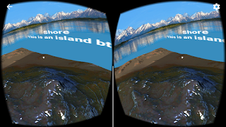
These are pictures and screenshots of the VR headset and apps I made in Unity. I used my iPhone 6S because its screen is bigger than my Samsung Galaxy S3 Mini.


Final_Project Diagram
Since I did not use the Arduino at all, I made a different diagram of my project:

-It shows the process of developing it, starting with the Google Cardboard SDK version 1.1.

-It shows the process of developing it, starting with the Google Cardboard SDK version 1.1.
Sunday, December 11, 2016
Final_Project[4] = MountainVR
-This is the last version
-I had a hard time to make the MainCamera see the Mountain. For some reason it was only seeing the skybox
-My original idea was to put the MainCamera above the highest mountain, so you can see the whole thing, but MainCamera would only see through the Mountain (and the entire GameObject).
Final_Project[3] = GazeInput
-This one took me a while to make it work.
-It is from a tutorial, but unfortunately, it used a very old version of the Google Cardboard SDK, so when I tried to use the scripts, Unity told me that they were deprecated and recommended to se the current versions.
-The ball was supposed to turn blue after 3 seconds of staring at it, but, again, with the current Google Cardboard SDK version, I had to add an Even Trigger System that only handles OnPointerEnter and OnPointerExit, even though GvrReticlePointer Script from the SDK has a OnPointerHover() function called every frame the user is still pointing at a valid GameObject, but I could not get it to work.
Final_Project[2] = MarsVR
-I found this really cool tutorial that explains how to create a skybox out of a panoramic view in Unity.
-I had to somehow tweak it because the Unity version used in the tutorial was an older one.
Final_Project[1] = Google Cardboard SDK
-This is something completely (and extremely) different from what I first wanted to do for the final project.
-My first idea was to just make a 2D game with the TFT screen like in the 2nd mini-project.
-I got a free VR Box (just paid shipping) so then I decided to make something with Virtual Reality
-The VR Box is similar to the Google Cardboard, but it does not have a physical Reticle or button that allows to perform screen touches. So I have to limit the mechanics to just staring at objects
-However, when testing it inside Unity, notice how I can do left click with the mouse when staring at the cube and it works fine.
-This is a scene that came with the Google Cardboard SDK for Unity (current version 1.1)
Thursday, December 8, 2016


Final Project: Demonstration
Final Project
I strayed from my original plan for my final project to be an abstract mirror. During my second mini-project critique, it was mentioned that it was like a windless wind chime, and that interested me. I decided to focus more on sound.
I wanted to subvert the relaxing nature of wind chimes, and to create an interactive thing that, the more someone interacted with it, the less they wanted to be around it. As a person got closer and spent more time around it, the motors would spin more violently and the sound of the chimes would evolve from soft and musical to more cacophonous. However, because my other motor couldn't spin the chimes, the sound never got that loud, and most people enjoyed it.

Final Project: Structure
The structure ended up being the downfall of the larger motor; it wasn't strong enough to do what I wanted it to.
I wanted the small motor to spin things within other things that the larger motor would be spinning. That wasn't possible because cables would get tangled. So I made a wooden gear essentially that would be turned by the motor and would allow the smaller motor to turn in the center of it.

 Later a kind of tap was added to the edge of the wood to give the motor head better traction.
Both motors are mounted with two brackets and a cable tie.
The structure was then mounted onto trimmed 2x4s nailed to plywood.

Finally the hanging components and circuitry were added. It was at this point I learned my motor wasn't strong enough. I later stained the wood black.

I wanted the small motor to spin things within other things that the larger motor would be spinning. That wasn't possible because cables would get tangled. So I made a wooden gear essentially that would be turned by the motor and would allow the smaller motor to turn in the center of it.


Both motors are mounted with two brackets and a cable tie.
The structure was then mounted onto trimmed 2x4s nailed to plywood.

Finally the hanging components and circuitry were added. It was at this point I learned my motor wasn't strong enough. I later stained the wood black.

Final Project: Circuitry Completed + Schematic
I put a separate transistor for each motor; I wasn't sure if it was safe or even possible to run two motors through one transistor.
For my schematics, I couldn't actually find the TTL Jpeg Camera in the components menu, so I used something with four connections in its place, one for ground, power, TX(output, to pin 2), and RX(input, to pin 3). This ended up being some gas sensor.
I also couldn't find the exact rangefinder, so used another rangefinder with three connections in its place.


Demonstration for completed circuitry.
For my schematics, I couldn't actually find the TTL Jpeg Camera in the components menu, so I used something with four connections in its place, one for ground, power, TX(output, to pin 2), and RX(input, to pin 3). This ended up being some gas sensor.
I also couldn't find the exact rangefinder, so used another rangefinder with three connections in its place.


Final Project: Distance Sensor
The other input besides motion detection that I wanted was distance. I mapped the analog input of the sonar rangefinder to the speed of the motor so that the closer something was, the faster the motor went.
The rangefinder can sometimes seem a little unreliable. It will occasionally jump between huge values even though what it's looking at hasn't come any closer.
Demonstration
The smaller motor will be linked to the rangefinder, and the larger motor, to the motion detector.
The rangefinder can sometimes seem a little unreliable. It will occasionally jump between huge values even though what it's looking at hasn't come any closer.
Demonstration
The smaller motor will be linked to the rangefinder, and the larger motor, to the motion detector.
Final Project: Motion Detection
Motion detection played a big part in my last gesture, and I wanted to include it in my final as well. However, instead of it being "Motion detected = move, no motion = stay still," I wanted the motor linked to the motion detector to spin faster the longer it detected motion.
My code for it looks like this:
if (cam.motionDetected()) {
Serial.println("Motion!");
cam.setMotionDetect(false);
digitalWrite(motionLED, HIGH);
if (motorSpeed < 255) {
motorSpeed++;
}
delay(200);
cam.resumeVideo();
cam.setMotionDetect(true);
} else if (! cam.motionDetected()) {
Serial.println("Still.");
digitalWrite(motionLED, LOW);
//analogWrite(motionMotor, 0);
delay(200);
if (motorSpeed > 29) {
motorSpeed--;
}
if (motorSpeed == 30) {
motorSpeed = 0;
}
} else {
//analogWrite(motionMotor, 0);
//motorSpeed = 0;
}
Demonstration
The motionLED is the blue LED; I included it because sometimes the motion detector doesn't work; I can't quite figure out when it won't.
For each moment it detects motion, it increments speed by one:

Wednesday, December 7, 2016
Final Project Process 5/5
Post Crit Thoughts:
The FSR worked to some extent. The piezo wasn't screeching like a hellbent banshee, so I'm marginally happy about that. The LEDs worked as anticipated. I only wish I had a pedestal for each of them to be situated on opposite sides of the room like a gallery space. Also, in a perfect world, I would have done as Juan suggested and connected the proximity sensor to a plant lamp so as to "give the plant life" with the attention you give it.
The FSR worked to some extent. The piezo wasn't screeching like a hellbent banshee, so I'm marginally happy about that. The LEDs worked as anticipated. I only wish I had a pedestal for each of them to be situated on opposite sides of the room like a gallery space. Also, in a perfect world, I would have done as Juan suggested and connected the proximity sensor to a plant lamp so as to "give the plant life" with the attention you give it.
Week 16 Final Project


int ledPin1=13;
int ledPin2=12;
int ledPin3=11;
int ledPin4=10;
int ledPin5=9;
int ledPin6=8;
int ledPin7=7;
int ledPin8=6;
int ledPin9=5;
int ledPin10=4;
int ledPin11=3;
int ledPin12=2;
int sensorPin=0;
float alpha=0.75;
int period=50;
float change=0.0;
void setup()
{
// Built-in arduino board pin
pinMode(ledPin1,OUTPUT);
pinMode(ledPin2,OUTPUT);
pinMode(ledPin3,OUTPUT);
pinMode(ledPin4,OUTPUT);
pinMode(ledPin5,OUTPUT);
pinMode(ledPin6,OUTPUT);
pinMode(ledPin7,OUTPUT);
pinMode(ledPin8,OUTPUT);
pinMode(ledPin9,OUTPUT);
pinMode(ledPin10,OUTPUT);
pinMode(ledPin11,OUTPUT);
pinMode(ledPin12,OUTPUT);
Serial.begin(9600);
Serial.print("Heartrate detection.\n");
delay(100);
}
float max =0.0;
void loop()
{
static float oldValue=1009;
static float oldChange=0.2;
// This is generic code provided with the board.
int rawValue=analogRead(sensorPin);
float value= alpha*oldValue +(1-alpha)* rawValue;
change=value-oldValue;
// Display data on the LED via a blip:
// Empirically, if we detect a peak as being X% from
// absolute max, we find the pulse even when amplitude
// varies on the low side.
// Reset max every time we find a new peak
if (change >= max) {
max= change;
Serial.println(" |");
digitalWrite(ledPin1,1);
digitalWrite(ledPin2,1);
digitalWrite(ledPin3,1);
digitalWrite(ledPin4,1);
digitalWrite(ledPin5,1);
digitalWrite(ledPin6,1);
digitalWrite(ledPin7,1);
digitalWrite(ledPin8,1);
digitalWrite(ledPin9,1);
digitalWrite(ledPin10,1);
digitalWrite(ledPin11,1);
digitalWrite(ledPin12,1);
} else {
Serial.println("|");
digitalWrite(ledPin1,0);
digitalWrite(ledPin2,0);
digitalWrite(ledPin3,0);
digitalWrite(ledPin4,0);
digitalWrite(ledPin5,0);
digitalWrite(ledPin6,0);
digitalWrite(ledPin7,0);
digitalWrite(ledPin8,0);
digitalWrite(ledPin9,0);
digitalWrite(ledPin10,0);
digitalWrite(ledPin11,0);
digitalWrite(ledPin12,0);
}
// Slowly decay max for when sensor is moved around
// but decay must be slower than time needed to hit
// next heartbeat peak.
max = max * 0.98;
// Display debug data on the console
// Serial.print(value);
// Serial.print(", ");
// Serial.print(change);
// Serial.print(", ");
// Serial.println(max);
oldValue=value;
oldChange=change;
delay(period);
}
Final Project Process 5/5
A proximity sensor turns on when the viewer is close to the box and then the viewer can see clearly what's inside. A mystery black box on a wall which contains my DCF (Florida Department of Children & Families) papers when I was in foster care. I decided to only use the significant ones such as in one in 1999 that my birthmother didn't show up to the visit. One in 2000 that the visit with my brother and birthmother went really well. Lastly, in 2001 when my adoption was finalized. In my experience as an adoptee, most people don't really know the foster system that well. Most people believe it's an orphanage of some-sort that the government runs which isn't true at all. The papers inside have a semi-gloss to them to represent self-identity and help the blue light bounce around inside the box. The blue light represents National Foster Care Month which is in May. It is symbolized with a blue ribbon.


const int signalPin= 0; //yellow wire connects to analog pin A0
const int LEDPin= 12; //LED connects to digital pin 13
int signal;//this variable, signal, will hold the analog value read by the arduino
void setup() {
Serial.begin(9600); //sets the baud rate for data transfer in bits/second
pinMode(signalPin, INPUT); //the infrared sensor signal line will be an input to the arduino
pinMode(LEDPin, OUTPUT); //the LED serves an output in the circuit
}
void loop() {
signal= analogRead(signalPin); //arduino reads the value from the infrared sensor
Serial.println(signal); //prints out analog value
delay(500); //delays the next analog reading by 500 ms or a half a second
if(signal > 199){ //if the analog value is less than 200, the object is within a few inches
digitalWrite(LEDPin, HIGH);
}
else{
digitalWrite(LEDPin, LOW);
}
}


Final Project Process 4/5
Link to vimeo here proving my bits are actually functional. I was fumbling between a FSR and a piezo to detect vibrations coming through the base of the plant. The issue was that the piezo was too sensitive and the FSR wasn't sensitive enough. I figured I could just pop out the resistors to give the FSR more juice to make it more receptive, but I was mistaken. I had to SQUEEZE the FSR between my fingers to elicit much of anything. The piezo was sensitive enough, but once it detected a vibration, the value it detected in the serial monitor wouldn't climb back to zero even if the stimulation stopped. So if I were to isolate a particular value, it would still scream for forever.
But my bits are hypothetically functional.. just incompetent.
But my bits are hypothetically functional.. just incompetent.
12/6 Final Project Process 3
After many hours of changing Piezos, switching wires, and having to deal with one of the Arduinos basically failing on me, I have come to a sort of final destination for my piece. I had to attach the Piezo to the side of a bag in order for it to detect any vibrations. However, its range is extremely finnicky and changes almost every time I plug the Arduino in. I didn't know how to deal with this. How you're supposed to have the wires plugged in apparently changes sometimes, too. Nothing was, or is, constant.
Nevertheless, at this point I have found out how to make the Piezo measure vibrations in a range. I will just have to edit the code accordingly right before class in order to match up with whatever range of values it decides to give me then. I have the space in Unity all set up, and no matter what happens, it will work to an extent. It's just a matter of having accurate interactivity. This was a pain. I am happy with what I've done in Unity, however.
Eh, sorry in advance.
Tuesday, December 6, 2016
Week 16 | Final Project Update 3/5


Week 1 Homework August 24, 2016 |
Read pages 1-36 in Tha Manga Giude to Electricity and post questions to blog.
Book has been ordered.
Appliances:
1. Hair dryer
watts
amps
volts
2. Crock Pot
watts
amps
volts
3. Microwave
watts
amps
volts
4. Toaster
watts
amps
volts
5. Cable Box
watts
amps
volts
What is the directional relationship between charge and current?
Book has been ordered.
Appliances:
1. Hair dryer
watts
amps
volts
2. Crock Pot
watts
amps
volts
3. Microwave
watts
amps
volts
4. Toaster
watts
amps
volts
5. Cable Box
watts
amps
volts
What is the directional relationship between charge and current?
Week 4 Mon. September 12, 2016 | DIY Variable Resistors Homework
Create a graphite drawing and connect it to an LED. Control the intensity of the light using the positive and negative lead cables and your breadboard. Make the drawing interesting and bring it to class on Wednesday.
Monday, December 5, 2016
Final Project Update 1-5 | Xiaoxi Zheng
Final Interface Design
Below is the final interface design for my project "Ebook". It highly resembles the interface for the popular social media Facebook. Inside the profile picture box would be a picture being generated by anyone who approaches this installation. This box in the virtual space will also have a resembling counterpart in the physical world. A box will be taped out in the physical world to formulate a boundary to invite any viewer to step inside.

The idea for this project is to compare and contrast how names and identities are recorded throughout history and to question the identity represented in the online social media presence today. As part of my personal background, I know every baby born in the countryside of South Eastern part of China was recorded in a family history book. These different family history books are one of the most well-documented records of Chinese history. This entity will be represented with the static 3D printed book on the "pedestal" on top of the bookshelf. The LEDs inside the book are again the colors of a sunset, representing the sunsetting of this old tradition. On the other hand, the interactive profile page represents how entities are formulated and represented in today's modern digital world.
I will let the installation itself to invite different individuals to approach and leave a brief moment of identity inside this mocked up social media site. Although ultimately there will be different viewers and audiences that will be stepping inside of this box, there remains one catch-all profile name and a generic interactive profile picture being generated. In the modern day era, from time to time identities becomes something clustered into big data, and individuals seem to be "averaged" against other consumer/user behavior metrics. I will leave the ultimate profile image representation as a surprise until demo day.
I've also attached a sketch of what the actual installation will look like. It will be largely composed of a bookshelf with the physical book I made from mini project one, and a projection of the above image.


Final project update 1
I'm working to create a force sensor that plays audio files when activated. It gives an value between 260 and 900 and, depending on what value it sends to the arduino, it plays a variable audio file. Here is the code I'm using.
*********
#include <FatReader.h>
#include <SdReader.h>
#include <avr/pgmspace.h>
#include "WaveUtil.h"
#include "WaveHC.h"
SdReader card; // This object holds the information for the card
FatVolume vol; // This holds the information for the partition on the card
FatReader root; // This holds the information for the filesystem on the card
FatReader f; // This holds the information for the file we're play
WaveHC wave; // This is the only wave (audio) object, since we will only play one at a time
#define DEBOUNCE 5
int fsrPin = 0; // the FSR and 10K pulldown are connected to a0
int fsrReading; // the analog reading from the FSR resistor divider
byte buttons[] = {14};
#define NUMBUTTONS sizeof(buttons)
volatile byte pressed[NUMBUTTONS], justpressed[NUMBUTTONS], justreleased[NUMBUTTONS];
int freeRam(void)
{
extern int __bss_end;
extern int *__brkval;
int free_memory;
if((int)__brkval == 0) {
free_memory = ((int)&free_memory) - ((int)&__bss_end);
}
else {
free_memory = ((int)&free_memory) - ((int)__brkval);
}
return free_memory;
}
void sdErrorCheck(void)
{
if (!card.errorCode()) return;
putstring("\n\rSD I/O error: ");
Serial.print(card.errorCode(), HEX);
putstring(", ");
Serial.println(card.errorData(), HEX);
while(1);
}
void setup() {
byte i;
// We'll send debugging information via the Serial monitor
Serial.begin(9600);
putstring("Free RAM: "); // This can help with debugging, running out of RAM is bad
Serial.println(freeRam()); // if this is under 150 bytes it may spell trouble!
pinMode(2, OUTPUT);
pinMode(3, OUTPUT);
pinMode(4, OUTPUT);
pinMode(5, OUTPUT);
pinMode(13, OUTPUT);
for (i=0; i< NUMBUTTONS; i++) {
pinMode(buttons[i], INPUT);
digitalWrite(buttons[i], HIGH);
}
if (!card.init()) { //play with 8 MHz spi (default faster!)
putstring_nl("Card init. failed!"); // Something went wrong, lets print out why
sdErrorCheck();
while(1); // then 'halt' - do nothing!
}
card.partialBlockRead(true);
// Now we will look for a FAT partition!
uint8_t part;
for (part = 0; part < 5; part++) { // we have up to 5 slots to look in
if (vol.init(card, part))
break; // we found one, lets bail
}
if (part == 5) { // if we ended up not finding one :(
putstring_nl("No valid FAT partition!");
sdErrorCheck(); // Something went wrong, lets print out why
while(1); // then 'halt' - do nothing!
}
putstring("Using partition ");
Serial.print(part, DEC);
putstring(", type is FAT");
Serial.println(vol.fatType(),DEC); // FAT16 or FAT32?
// Try to open the root directory
if (!root.openRoot(vol)) {
putstring_nl("Can't open root dir!"); // Something went wrong,
while(1); // then 'halt' - do nothing!
}
// Whew! We got past the tough parts.
putstring_nl("Ready!");
TCCR2A = 0;
TCCR2B = 1<<CS22 | 1<<CS21 | 1<<CS20;
//Timer2 Overflow Interrupt Enable
TIMSK2 |= 1<<TOIE2;
}
SIGNAL(TIMER2_OVF_vect) {
check_switches();
}
void check_switches()
{
static byte previousstate[NUMBUTTONS];
static byte currentstate[NUMBUTTONS];
byte index;
for (index = 0; index < NUMBUTTONS; index++) {
currentstate[index] = digitalRead(buttons[index]); // read the button
/*
Serial.print(index, DEC);
Serial.print(": cstate=");
Serial.print(currentstate[index], DEC);
Serial.print(", pstate=");
Serial.print(previousstate[index], DEC);
Serial.print(", press=");
*/
if (currentstate[index] == previousstate[index]) {
if ((pressed[index] == LOW) && (currentstate[index] == LOW)) {
// just pressed
justpressed[index] = 1;
}
else if ((pressed[index] == HIGH) && (currentstate[index] == HIGH)) {
// just released
justreleased[index] = 1;
}
pressed[index] = !currentstate[index]; // remember, digital HIGH means NOT pressed
}
//Serial.println(pressed[index], DEC);
previousstate[index] = currentstate[index]; // keep a running tally of the buttons
}
}
void loop() {
byte i;
fsrReading = analogRead(fsrPin);
Serial.print("fsrReading=");
Serial.print(fsrReading);
delay(200);
if (justpressed[0] && fsrReading < 280) {
justpressed[0] = 0;
}
else if (justpressed[0] && fsrReading > 800) {
justpressed[0] = 0;
playcomplete("CARLIN02.WAV");
}
else if (justpressed[0] && fsrReading > 770) {
justpressed[0] = 0;
playcomplete("CARLIN03.WAV");
}
else if (justpressed[0] && fsrReading > 740) {
justpressed[0] = 0;
playcomplete("CARLIN04.WAV");
}
else if (justpressed[0] && fsrReading > 710) {
justpressed[0] = 0;
playcomplete("CARLIN05.WAV");
}
else if (justpressed[0] && fsrReading > 680) {
justpressed[0] = 0;
playcomplete("CARLIN06.WAV");
}
else if (justpressed[0] && fsrReading > 650) {
justpressed[0] = 0;
playcomplete("CARLIN01.WAV");
}
else if (justpressed[0] && fsrReading > 620) {
justpressed[0] = 0;
playcomplete("CARLIN07.WAV");
}
else if (justpressed[0] && fsrReading > 590) {
justpressed[0] = 0;
playcomplete("CARLIN08.WAV");
}
else if (justpressed[0] && fsrReading > 560) {
justpressed[0] = 0;
playcomplete("CARLIN09.WAV");
}
else if (justpressed[0] && fsrReading > 530) {
justpressed[0] = 0;
playcomplete("CARLIN19.WAV");
}
else if (justpressed[0] && fsrReading > 500) {
justpressed[0] = 0;
playcomplete("CARLIN11.WAV");
}
else if (justpressed[0] && fsrReading > 470) {
justpressed[0] = 0;
playcomplete("CARLIN12.WAV");
}
else if (justpressed[0] && fsrReading > 440) {
justpressed[0] = 0;
playcomplete("CARLIN13.WAV");
}
else if (justpressed[0] && fsrReading > 410) {
justpressed[0] = 0;
playcomplete("CARLIN14.WAV");
}
else if (justpressed[0] && fsrReading > 380) {
justpressed[0] = 0;
playcomplete("CARLIN15.WAV");
}
else if (justpressed[0] && fsrReading > 350) {
justpressed[0] = 0;
playcomplete("CARLIN16.WAV");
}
else if (justpressed[0] && fsrReading > 320) {
justpressed[0] = 0;
playcomplete("CARLIN17.WAV");
}
else if (justpressed[0] && fsrReading > 290) {
justpressed[0] = 0;
playcomplete("CARLIN18.WAV");
}
}
void playcomplete(char *name) {
// call our helper to find and play this name
playfile(name);
while (wave.isplaying) {
// do nothing while its playing
}
// now its done playing
}
void playfile(char *name) {
// see if the wave object is currently doing something
if (wave.isplaying) {// already playing something, so stop it!
wave.stop(); // stop it
}
// look in the root directory and open the file
if (!f.open(root, name)) {
putstring("Couldn't open file "); Serial.print(name); return;
}
// OK read the file and turn it into a wave object
if (!wave.create(f)) {
putstring_nl("Not a valid WAV"); return;
}
// ok time to play! start playback
wave.play();
}
Sunday, December 4, 2016
Week 16 | Final Project Update 2/5
Since I started working on this at home, I left my 9v battery on campus. I used my laptop to power up the motor and it seemed to be working fine.


However, after taking the video the motor seemed to not be speeding up when I moved the potentiometer. When I get back to campus, I plan on hooking up the battery and using that as the power source, hopefully the speed increases.
For now I'm following the zoetrope guidelines found in the arduino project book. I started building the pinwheel exercise as a reference, but I plan on buying card stock paper in other colors and tracing the template. My goal for now is to have this moving and working. I am still trying to figure out a way to enclose the wires and the arduino board. My challenge is going to be figuring out how to hold the motor upright in place with some sort of stand...
Subscribe to:
Posts (Atom)