Materials -
mic, touching it causing the light to react signifying it works
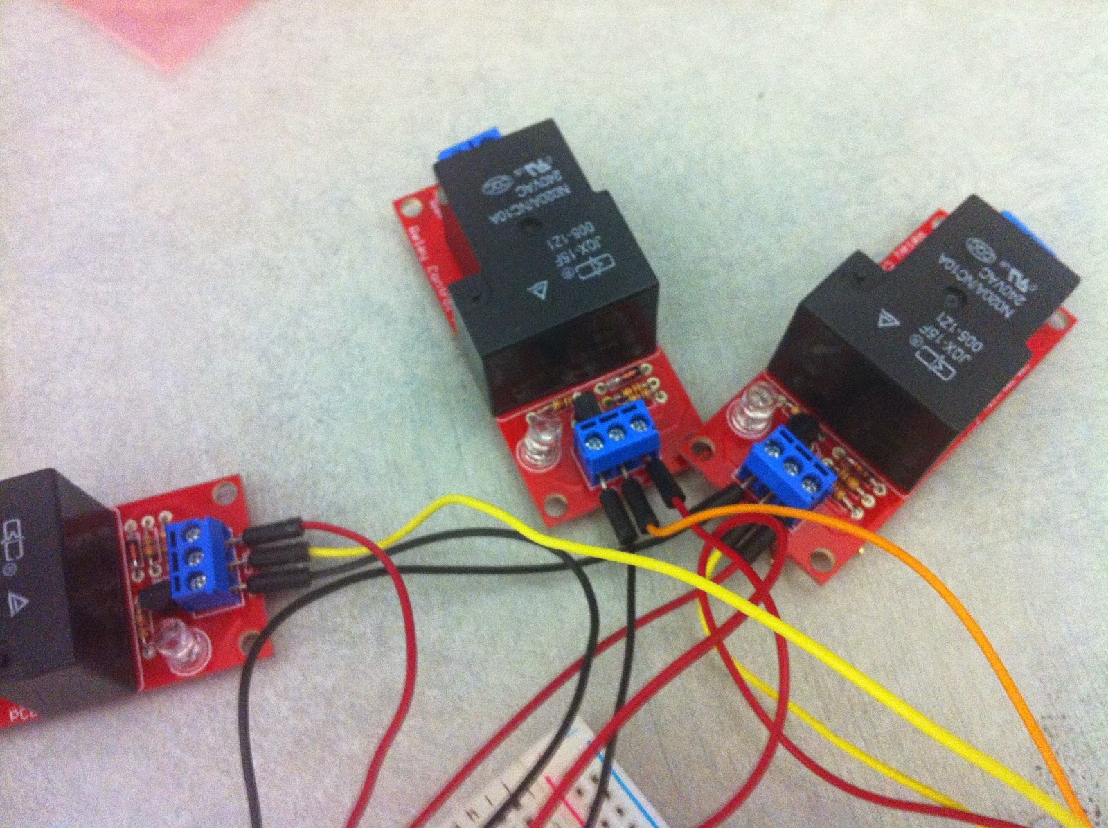
relay built with package materials, clicking signifying it works
street light, powered by outlet and 3 wires to each color
arduino with cables attatched to gnd and 5v as well as 9, 10 , 11 for diff relays
connecting 3 relays to arduino and breadboard
testing relays
connecting mic to arduino and breadboard
testing it on street light
soldering and stretch wrapping arduino and wires
adding potentiometer to control volume sensitivity

Fitting it all in a box, drilling holes in box for wiring and potentiometer
building hanger on back of street light to hang from door using metal rods, rope, hooks, and screws
final testing
testing lcd screen on breadboard before soldering
labeling wires to pins with tape to ready for soldering
soldering wires to arduino and breadboard adding shrinking wrap to keep wires together and organized
expiriencing problems with lcd screen due to short
testing lcd screen after soldering after fixing short
testing reverse code on red light
final look on door ready for presentation
documentation
Overall satisfied with the final process.
Feed back recieved included using different words in the LCD screenperhaps having it switch with a relay depending on the light triggered.
Changes - red light was reverse coded and LCD screen was soldered on to give a more
visual representation of the process occuring. Conceptually I felt it added to the project more
because people were better able to interact with project by simply knocking.
A couple shorting problems occured but were able to be fixed by clipping away touching solders


.JPG)
.JPG)
.JPG)
.JPG)
.JPG)
No comments:
Post a Comment