
Monday, October 31, 2011

Renate, Ryan, Emily- Project 19 and 20
With our powers combined.... we did this:
A Photo of our setup

Project 19
Project 20
A Photo of our setup

Project 19
Project 20
pin layout for led grid
Here's a PDF of the pin / columns / row layout for the TOM - 1088MR - B led grid.
http://www.mediafire.com/file/5ho7fes936omvtx/tom_1088bmr_b_pin_label.pdf
The first sheet is a diagram. The second sheet has an 8x8 grid to sketch designs to be animated.
Enjoy!
-Dan
http://www.mediafire.com/file/5ho7fes936omvtx/tom_1088bmr_b_pin_label.pdf
The first sheet is a diagram. The second sheet has an 8x8 grid to sketch designs to be animated.
Enjoy!
-Dan
Sunday, October 30, 2011
Kelsey's Final Proposal
I'm still hazy on details, but I want to include C9 bulbs, micro switches and motors perhaps? I'm interested in creating a 'program' or pattern without the Arduino.


Final Project thoughts
Haven't gotten to far in respect to the final project, but Me, Ryan, and Emily have all discussed working together again and expanding on the possibilities of the EEG sensor via the Mindflex.
So far we've briefly discussed it, so no specific ideas as of yet.
So far we've briefly discussed it, so no specific ideas as of yet.
Wednesday, October 26, 2011


My final project idea.
I thinking of doing a project utilizing a flex sensor and motors.
The flex sensor will be outside and in a high up place so that it will be caught by wind. When it is caught by wind it will activate a motor which will power a fan indoors.
Wind power controlling wind power.
The flex sensor will be outside and in a high up place so that it will be caught by wind. When it is caught by wind it will activate a motor which will power a fan indoors.
Wind power controlling wind power.
Tuesday, October 25, 2011
Ovu and Aphrodite
Though short, the two examples provided in this short news story http://www.furtherfield.org/reviews/ovu-and-aphrodite-mobilefest
are quite thought-provoking. I was curious about the accuracy of the Basal Body Temperature read by the thermistor and how this was art, and not a commercial piece. The idea of disguising instead of stripping down the technology seemed like the job of a commercial designer not an artist. The shoes on the other hand seemed more artistic since the designer included a statement of purpose. "Platforms is designed to question moral attitudes and value judgments" I think that by selecting a specific group of people and making a social commentary on a different aspect of safety versus legality, we re-humanize the somewhat dehumanized.
LCD Projects- Renate and Emily
After spending a whole class troubleshooting I got the LCD screen to work! YAY!
However, I feel like there must be something wrong with the Thermistor for project 24... I could be wrong, but I don't think its that hot in here...

UPDATE: Got the thermistor to work properly. There was nothing wrong with it, I had put the resistor in the wrong way.
However, I feel like there must be something wrong with the Thermistor for project 24... I could be wrong, but I don't think its that hot in here...

UPDATE: Got the thermistor to work properly. There was nothing wrong with it, I had put the resistor in the wrong way.
Lin and Kelsey Final Doc
I'd love the footage that was taken of the class interacting with that if someone would comment on the post!
Interactive LED Light Box from K. Olson on Vimeo.
Interactive LED Light Box from K. Olson on Vimeo.
Monday, October 24, 2011

Wednesday, October 19, 2011
"Letting Go" Emily, Renate, Ryan Project Discussion
Due to the running out of time in class below please leave your comments and suggestions about our project below. Thank you all.
Shirts! And Stuff!

For those that were interested here's my shirt website
if you want a shirt, or a shirt in a certain color, let me know as I can change the shirt colors as well as discount the prices.
it's in progress but going to be an extension of my artist site.


Tuesday, October 18, 2011
IR Sensor Overview

First and foremost, IR Sensors (ie. Infrared Sensors) are awesome due to the unique nature in which they can act as an I/O switch. For our table project we are using a IR Light Barrier Kit (similar to the one pictured above) in order to detect the presence of a person in the vicinity.
The IR Sensor is split into two parts: The IR Emitter and the IR Detector. The Function of the Emitter is basic; It holds two IR LEDs that are constantly on when in use. The IR
Detector is where the magic works. When set to have its primary LED sensor facing the IR Emitter's LEDs (up to 13ft) it stays in a powered off state, or in terms of a switch, an open switch. As soon as something blocks or breaks the path of the IR lights on the Emitter the state of the Detector is set to on, or a closed switch. When closed it activates a + and - output on the Detector board. For our project this is where we communicate with the Arduino/Motor Shield.

Our Arduino/Motor Shield receives the signal from the IR sensor weather it is in + or - state. When in - state, or LOW state, the Arduino/Motor Shield does nothing. When in + state, or HIGH state, the Arduino/Motor Shield begins to respond. It runs code to then send signals to a stepper motor that it is connected to, which in turn will have effect over the table we have the motor built into.

This is a very basic summary of how the entire process works, but the goal we are focusing on is primarily less headaches and simple functional output.
wobbly table fritzing diagram

1. IR Sensors, placed at door way? or somewhere discrete
2. sensor triggers Arduino which plays code and powers motor via motor shield
3. Motor Shield goes here
4. motor is attached underneath table with weights or other mechanism for moving the table
Kelsey and Lin finishing up process work
Below is our process work detailed out, including videos and a little timeline I made. Looking back and finishing up, I think the audience will be curious to look in front of it. The LED's are so beautiful and engaging I can't help but stare at them. Unfortunately its a lot easier than we anticipated to trick the sensor into seeing the lights. Which is okay, the LED's are so beautiful that I feel kinda bad withholding them from people.
Overall we're pleased, the wood hails back to stretcher bars and wood framing somthing very crafty and hands on. I think it meshes nicely with the technology we are using like arduino, heat shields, wiring ect. The colors on the wall blend together nicely, harkening the viewer to come closer-they give off a magical sort of glow that will peek the viewers curiosity. The glow they make is an otherworldly glow.

Process Videos
so we've been taking video of our process, here are our successes (and a few fails)
:)
:)
Monday, October 17, 2011
Sensor Presentation
Here's our Presentation about the EEG sensor:
I had trouble getting the annotations to work,
Here are the links respectively
http://medicarduino.wordpress.com/category/eeg-brain-machine-interfaces/
Control TV/ control wheelchair
http://www.neurosky.com/Academics/University.aspx
artifical limb control/ ADHD studies/ Sleep disorders
http://www.neurosky.com/Academics/Education.aspx
monitors student's attention levels

Online Sensor presentation
o Pick one of the sensors that you are using in your group project.
o FSR: force sensing resistor
o How does it work?
o Force Sensing Resistors (FSR) are a polymer thick film (PTF) device which exhibits a decrease in resistance with an increase in the force applied to the active surface
o What different flavors does it come in?
o Shapes.
o What are its practical applications outside of art making?
o Human touch control in electronic devices
o Find as much information about that sensor as possible.
o http://www.media.mit.edu/resenv/classes/MAS836/Readings/fsrguide.pdf
o Locate the schematic.
o the top image is.
o Find the inputs, outputs, how to calibrate or impact the use and other relevant information on the diagram.
o Input is the force applied; Output is the voltage; RM can be of 3k, 10k, 30k, 47k and 100k and these different RMs correspond different output sets. The amplifier is another factor
o What are its power requirements and what sorts of other electronics are necessary to get it to work.
o 5v power supply and a resistor are necessary.
o Label the diagram and explain to us how to use the sensor.
o In my case, the amplifier is integrated in arduino and 10k resistor is good for my output range.
o Tell us how the sensor is typically used. Tell us how you plan to use and/or modify the sensor.
o According to the FSR guide, this sensor is not for weight and probably can be better used for human touching. In my situation, Repeatable and Reproducible Mechanical Actuation System is the CRUTIAL part.
Lin and Kelsey's Sonar Podcast
lin and I's podcast, had some trouble so sorry for the low quality and wired crop.
Some success... and some epic failure
This past Friday, Natalie and I were all set to go with installing our bench at an actual bus stop. We set out with our Arduino and speakers that we put in a nice little box to fit underneath the bench. We had decided to install at a smaller bus stop along Museum road, and we had gone out right after a class change, so there were not a whole lot of people out, which was perfect for installing. After asking an angry Asian girl on her cell phone to move off of our prospective bench and after some wrestling, we finally got everything into place and we supposedly set to go.
And that was when the problems began.
Our apparatus is brown, which matches the paint on the benches pretty closely. However, we did not take into account that some of the benches were not in good repair and that the paint was chipped off, making our apparatus much more conspicuous that we had originally hoped.
Natalie sat on the other bench about 15 feet away with her video camera hidden in her backpack while I sat on the bench with a voice recorder. I was sitting on the sensor, and... it wasn't going off, which was unfortunate, because some guy came and sat down on the bench next to me. When he sat down, he noticed the apparatus and started picking at it, so I tried to explain to him that it was a project, and that it wasn't working. I got up and checked the box with our equipment and noticed that the soldering on one of the battery terminals had broken. We quickly taped it up and fixed it.
Natalie resumed her position on the far bench while I sat on the sensor. This is when we realized we had another problem. The audio was playing, however, there was an error in the programming that caused the bench to continually play all the different clips while I was sitting on it and the contacts were touching. When I got up to tell Natalie, trouble arose...
In the five seconds that I had gotten off of the bench, some middle-aged dude came over to our bench to sit down. The apparatus came un-taped and rose up slightly. Instead of deciding not to sit on the bench, this guy proceeds to forcefully RIP our apparatus off of the bench, as if he were pulling some giant weed. Natalie and I watched in horror while this was happening, and we decided to pack up and call it a day.
The damage he did was not too extensive. One of our contacts became unglued and a little bit of the soldering had broken, however, we were able to repair the physical damage. We also went back to the code and fixed it.
So the main lesson that we learned was that our project is not public-proof. We are also trying to find a bus stop bench in better repair and plan to tape it down better next time. It is also important to supervise the project while it is on the bench. Unfortunately we didn't get the guy on film who destroyed our stuff, but I hope this account of it was amusing enough.
Needless to say, it was a failure, but we now have a few more considerations for our final project.
Sunday, October 16, 2011
And Sensors to Talk About
http://en.wikipedia.org/wiki/Tactile_sensor
http://en.wikipedia.org/wiki/Touch_switch
http://www.analog.com/library/analogDialogue/archives/40-10/cap_sensors.html
This makes most sense, but I believe someone else might be talking about it:
http://en.wikipedia.org/wiki/Force-Sensing_Resistor
http://en.wikipedia.org/wiki/Touch_switch
http://www.analog.com/library/analogDialogue/archives/40-10/cap_sensors.html
This makes most sense, but I believe someone else might be talking about it:
http://en.wikipedia.org/wiki/Force-Sensing_Resistor

Saturday, October 15, 2011
Lin and Kelsey LCD attempt
We tried a lower resistor, but all it did was make the screen brighter. Troubleshooted with other more simple code, but to no avail. The wiring is perfect, there's connections in the middle, but the book didn't address them at all so we're not sure what to do with them.

Bench Fritzing Circuit

Here is the Fritzing diagram for our bench project. We relied on a wave shield for our project, and Fritizing doesn't have that part, so let's use our imaginations here and pretend that it's a wave shield. Otherwise, Fritzing is pretty neat.
Thursday, October 13, 2011
Wobbly Table Progress Report
This is a long overdue update of our process.
While Sam was working on making the IR sensor work properly I was working with the stepper motor to see how to add weight to get the kind of movement we want for our table.
My first intuition was to use fishing line and bullet weights to create momentum to move the table.
I tried it with one weight...
and I tried it with a lot of weights (and every amount in-between).
Although the video with the most weights looks like it could work none of these seemed to make the motor itself move very much and I was concerned that the extra weight would not only be inconvenient and hard to work with but noisy as well.
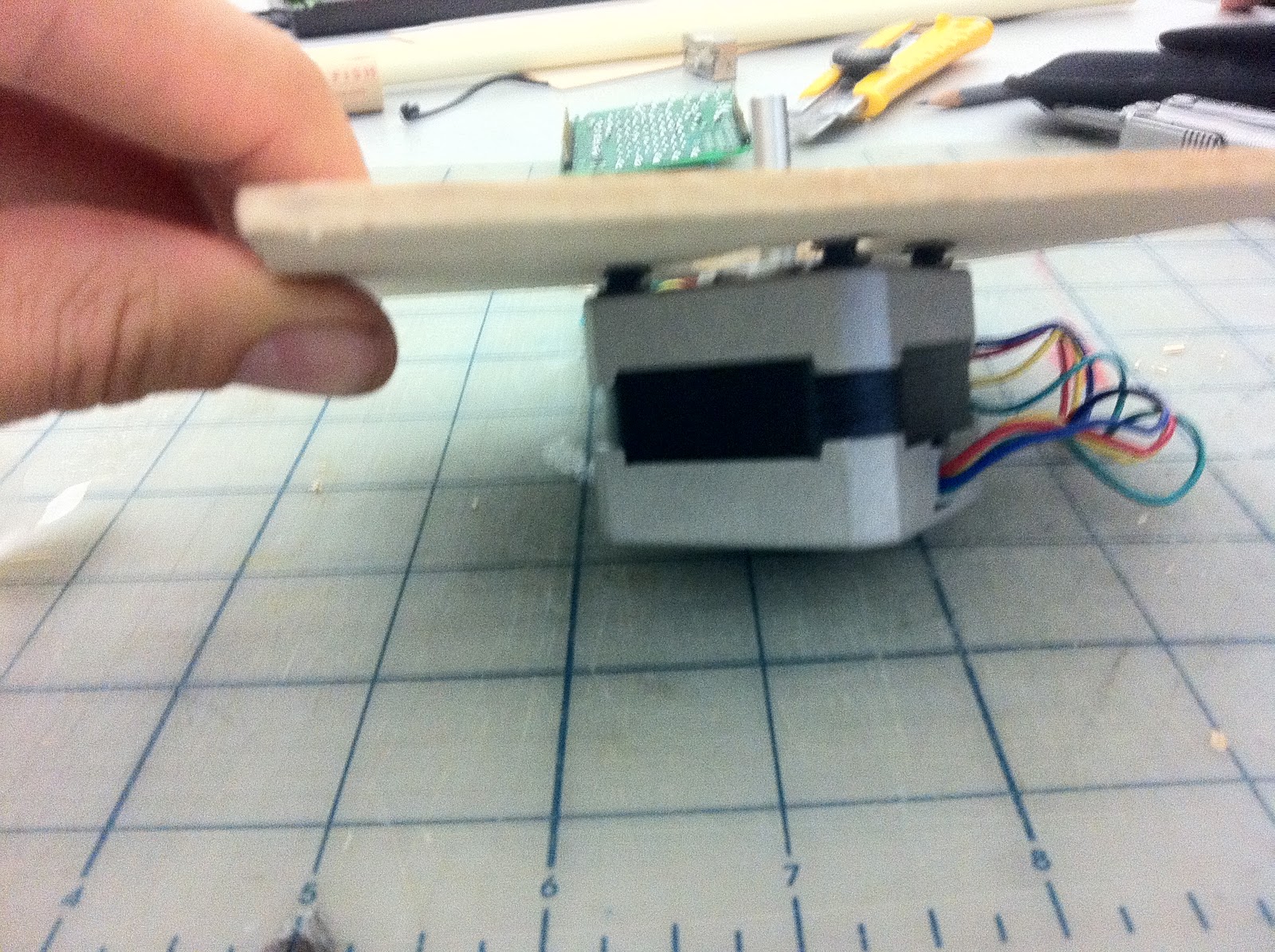
I tried using a balsa wood stick with one bullet weight on each end and VOILA! it worked like a charm.
The next day when Sam and I met he not only had the IR sensor working but had put together code that randomized the motor's movement.
Our next step was to figure out how to attach the motor to the table. We currently have the motor mounted to a piece of wood which we might screw or velcro (for easier access) to a hole we will make in the bottom of the table.


Once we attach the motor we can start messing with the code to make sure it affects the table just the way we want it to.
Sensoratiously yours,
Dan
While Sam was working on making the IR sensor work properly I was working with the stepper motor to see how to add weight to get the kind of movement we want for our table.
My first intuition was to use fishing line and bullet weights to create momentum to move the table.
I tried it with one weight...
and I tried it with a lot of weights (and every amount in-between).
Although the video with the most weights looks like it could work none of these seemed to make the motor itself move very much and I was concerned that the extra weight would not only be inconvenient and hard to work with but noisy as well.
I tried using a balsa wood stick with one bullet weight on each end and VOILA! it worked like a charm.
The next day when Sam and I met he not only had the IR sensor working but had put together code that randomized the motor's movement.
Our next step was to figure out how to attach the motor to the table. We currently have the motor mounted to a piece of wood which we might screw or velcro (for easier access) to a hole we will make in the bottom of the table.
screws and spacers

from the top
from the side

from the bottom, the velcro would go in each corner of the board
Once we attach the motor we can start messing with the code to make sure it affects the table just the way we want it to.
Sensoratiously yours,
Dan
Wednesday, October 12, 2011

A datasheet of the LCD
Hi, all,
just in case you'll need this.
http://www.sgbotic.com/products/datasheets/display/ADM1602K-1.pdf
just in case you'll need this.
http://www.sgbotic.com/products/datasheets/display/ADM1602K-1.pdf
And Just About Ready to Set Up At Bus Stop - Natalie, Netalia, Dailey
Finished circuit set up:
 Finished Code:

/*
NOTES:
 contact1 to digital 6 and 5V
 contact2 to digital 7 and 5V
 contact3 to digital 8 and 5V
 speaker to digital 9

 do note: requires waveHC library

 !!all audio needs to be 22KHz 16-bit .wavs at the most!!
 */
int contact1 = 6;
int contact2 = 7;
int contact3 = 8;
#include <WaveHC.h>
#include <WaveUtil.h>

SdReader card;    // This object holds the information for the card
FatVolume vol;    // This holds the information for the partition on the card
FatReader root;   // This holds the information for the volumes root directory
FatReader file;   // This object represent the WAV file
WaveHC wave;      // This is the only wave (audio) object, since we will only play one at a time

// time to play each tone in milliseconds
#define PLAY_TIME 61000

// Define macro to put error messages in flash memory
#define error(msg) error_P(PSTR(msg))
/*for test melody
 #include "pitches.h"  //this is just for testing noise
 int melody[] = {
 NOTE_C4, NOTE_G3,NOTE_G3, NOTE_A3, NOTE_G3,0, NOTE_B3, NOTE_C4};
 int noteDurations[] = {
 4, 8, 8, 4,4,4,4,4 };  // note durations: 4 = quarter note, 8 = eighth note, etc.:
 */
void setup() {
  Serial.begin(9600);
  pinMode(contact1, OUTPUT);
  pinMode(contact2, OUTPUT);
  pinMode(contact3, OUTPUT);
  pinMode(9, OUTPUT);
  if (!card.init()) error("card.init");
  // enable optimized read - some cards may timeout
  card.partialBlockRead(true);
  if (!vol.init(card)) error("vol.init");
  if (!root.openRoot(vol)) error("openRoot");
}

void loop() {
  int val1 = digitalRead(contact1);     //this is technically unnecessary, but seems to work better, so whatever
  int val2 = digitalRead(contact2);
  int val3 = digitalRead(contact3);
  if (val1 == HIGH | val2 == HIGH | val3 == HIGH){
    Serial.print("contact1:  "); //so we can see what's going on, but only if contact is made, otherwise it'd be a madhouse
    Serial.println(val1);
    Serial.print("contact2:  ");
    Serial.println(val2);
    Serial.print("contact3:  ");
    Serial.println(val3);
  }
  delay(20);  //slight delay between contact and play
  if (val1 == HIGH | val2 == HIGH | val3 == HIGH){
    /*PgmPrintln("Index files");
    indexFiles();

    PgmPrintln("Play files by index");
    playByIndex();
*/
PgmPrintln("Play files by name");
playByName();

    /*test melody
     for (int thisNote = 0; thisNote < 8; thisNote++) {
     int noteDuration = 1000/noteDurations[thisNote];
     tone(8, melody[thisNote],noteDuration);
     int pauseBetweenNotes = noteDuration * 1.30;
     delay(pauseBetweenNotes);
     }
     */
    delay(500);   //this will make it so if two people sit down almost at the same time, only one sound will play, but who knows
  }
  else {
  }
}
/*
 * print error message and halt
 */
void error_P(const char *str) {
  PgmPrint("Error: ");
  SerialPrint_P(str);
  sdErrorCheck();
  while(1);
}
/*
 * print error message and halt if SD I/O error, great for debugging!
 */
void sdErrorCheck(void) {
  if (!card.errorCode()) return;
  PgmPrint("\r\nSD I/O error: ");
  Serial.print(card.errorCode(), HEX);
  PgmPrint(", ");
  Serial.println(card.errorData(), HEX);
  while(1);
}
/*
char fileLetter[] =  {
  '0', '1', '2', '3', '4', '5', '6',
  '7', '8', '9', 'A', 'B', 'C', 'D', 'P', 'S'};

// index of DTMF files in the root directory
uint16_t fileIndex[FILE_COUNT];
*/
/*
 * Find files and save file index.  A file's index is is the
 * index of it's directory entry in it's directory file.
 */
/*void indexFiles(void) {
  char name[10];

   // copy flash string to RAM
   strcpy_P(name, PSTR("DTMFx.WAV"));

   for (uint8_t i = 0; i < FILE_COUNT; i++) {

   // Make file name
   name[4] = fileLetter[i];

   // Open file by name
   if (!file.open(root, name)) error("open by name");

   // Save file's index (byte offset of directory entry divided by entry size)
   // Current position is just after entry so subtract one.
   fileIndex[i] = root.readPosition()/32 - 1;
   }
  PgmPrintln("Done");
}
 // Play file by index and print latency in ms
void playByIndex(void) {
  for (uint8_t i = 0; i < FILE_COUNT; i++) {
    // start time
    uint32_t t = millis();
    // open by index
    if (!file.open(root, fileIndex[i])) {
      error("open by index");
    }
    // create and play Wave
    if (!wave.create(file)) error("wave.create");
    wave.play();
    // print time to open file and start play
    Serial.println(millis() - t);
    // stop after PLAY_TIME ms
    while((millis() - t) < PLAY_TIME);
    wave.stop();
    // check for play errors
    sdErrorCheck();
  }
  PgmPrintln("Done");
}*/
#define FILE_COUNT 6      //change these two things for audio files
char fileLetter[] =  {'0', '1', '2', '3', '4', '5'};
int i = 0;
void playByName(void) {
  char name[10];
  // copy flash string to RAM
  strcpy_P(name, PSTR("ABBAx.wav"));
//  for (uint8_t i = 0; i < FILE_COUNT; i++) {
    // start time
    uint32_t t = millis();
    // make file name
    name[4] = fileLetter[i];
    Serial.println(name);
    // open file by name
    if (!file.open(root, name)) error("open by name");
    // create wave and start play
    if (!wave.create(file)) error("wave.create");
    wave.play();
    // print time
    Serial.println(millis() - t);
    // stop after PLAY_TIME ms
    while((millis() - t) < PLAY_TIME);
    wave.stop();
    // check for play errors
    sdErrorCheck();
    i++;  //this was me, so it plays next file next person
    if (i == FILE_COUNT) {
      i = 0;
    }     //this will make it start over when it hits last defined file
//  }
  PgmPrintln("Done");
}
online sensor presentation-1: FSR Sensor
The FSR is made of 2 layers seperated by a spacer. The more one presses, the more of those Active Element dots touch the semiconductor and that makes the resistance go down

What is a Force Sensitive Resistor?
FSRs are sensors that allow you to detect physical pressure, squeezing and weight. They are simple to use and low cost.
FSR's are basically a resistor that changes its resistive value (in ohms Ω) depending on how much its pressed. These sensors are fairly low cost, and easy to use but they're rarely accurate. They also vary some from sensor to sensor perhaps 10%. So basically when you use FSR's you should only expect to get ranges of response. While FSRs can detect weight, they're a bad choice for detecting exactly how many pounds of weight are on them.
However, for most touch-sensitive applications like "has this been squeezed or pushed and about how much" they're a good deal for the money!
How will use the sensor in our project?
We used 4 FSR as one large force sensor that connect to a MP3 player shield.
Please read more on the lu's next post
Project 23 Beginning Arduino

Glowing display


Netalia's display (x3)
LCD display totally glows!!!!..... and does nothing else.
After troubleshooting/ trying the example codes titled Serial Display, HelloWorld, setCursor, we came to the conclusion that this is not going to work.
We read the datasheet at http://www.sparkfun.com/datasheets/LCD/HD44780.pdf and didn't find any more helpful information. Renate and I both got ours to glow, Renate with male pins, and I with the wires tilted precariously in the breadboard. Netalia got hers to glitch with some display with a different tilt, but none got it to work.
Dan noticed that the back had the reverse placements for +/- but it still only glowed.


Being Productive on Monday 10/10
Evidence of showing up on Monday 10/10 and working on our project in Katerie's absence-
We worked on soldering an extra motor shield for our project's ardunio,

We also discussed many aspects of our project, including:
- A decision based on the classes in progress crit to NOT pop the balloon, but let it go outside
- A quick internet search, and a phone call to Party City about bio-degradable balloons (apparently all latex balloons are bio-degradable)
- The use of an electrical cord to assist our motor and where those plugs can be found outside
- Setting up a gear system to rotate a spool and release the string attached to the balloon
-How the data we receive from the Mindflex will rotate the motor, and the use of a DC motor instead of a stepper motor
- Using a lightweight and bio-degradable string attached to the balloon, probably Raffia (which is very available right now b/c of it being the fall season)
-The design of a box to cover motor and make it look prettier
-The ordering of an extra long (16ft) USB cable so that the person wearing the headset has mobility while still being plugged in
-Our schedule of times to meet up until the due date
-Our own personal to-do lists
I have been the official note-taker for the group, I will upload some sketches, diagrams, lists and other pages from my notebook soon!

Tuesday, October 11, 2011
Monday, October 10, 2011
And More Progress - Dailey, Netalia, Natalie
Code is just about set, working on wave shield class:
/*
NOTES:
contact1 to digital 6 and 5V
contact2 to digital 7 and 5V
contact3 to digital 8 and 5V
speaker to digital 9 for test melody
speaker to 9 for SD card- NOT FUNCTIONAL NOW
!!all audio needs to be 22KHz or 16-bit .wavs at the most!!
*/
#include "pitches.h" //this is just for testing noise
int contact1 = 6;
int contact2 = 7;
int contact3 = 8;
int speaker = 9;
//for test melody
int melody[] = {
NOTE_C4, NOTE_G3,NOTE_G3, NOTE_A3, NOTE_G3,0, NOTE_B3, NOTE_C4};
int noteDurations[] = {
4, 8, 8, 4,4,4,4,4 }; // note durations: 4 = quarter note, 8 = eighth note, etc.:
void setup() {
Serial.begin(9600);
pinMode(contact1, OUTPUT);
pinMode(contact2, OUTPUT);
pinMode(contact3, OUTPUT);
pinMode(9, INPUT); //connect speaker to 9 to play test melody
Serial.println("hello world");
}
void loop() {
int val1 = digitalRead(contact1); //this is technically unnecessary, but seems to work better, so whatever
int val2 = digitalRead(contact2);
int val3 = digitalRead(contact3);
if (val1 == HIGH | val2 == HIGH | val3 == HIGH){
Serial.print("contact 1 ");
Serial.println(val1); //so we can see what's going on, but only if contact is made, otherwise it'd be a madhouse
Serial.print("contact 2 ");
Serial.println(val2);
Serial.print("contact 3 ");
Serial.println(val3);
}
delay(20); //slight delay between contact and play
if (val1 == HIGH | val2 == HIGH | val3 == HIGH){ //works so all of the triggers work together
//test melody
for (int thisNote = 0; thisNote < 8; thisNote++) { int noteDuration = 1000/noteDurations[thisNote]; tone(speaker, melody[thisNote],noteDuration); int pauseBetweenNotes = noteDuration * 1.30; delay(pauseBetweenNotes); } delay(50); //modify time: this will make it so if two people sit down almost at the same time, only one sound will play, but who knows }
else { } }
Building the bench piece in order to install it.
As a result of suggestions and discussions on Wednesday, we can now articulate a rather valid idea.
The but stop itself is important location (as we have mentioned time and time again), so we finally concluded to focus on the idea of the space itself.
As Marc Auge has been haunting our ideas with his theories, it is only fair to mention the idea of the non-place....which is exactly what the bus stop is. Non-place being: "If place can be defined as relational, historical and concerned with identity, then a space which can not be defined as relational, or historical, or concerned with identity will be a non-place."
So, the idea is how people perceive space, and what makes a certain space the space it is. Why is a bus stop a bus stop? If there were famous images of modern art hanging from the bus stop would it be a gallery? What decides what the space is? If someone is told that a space is a museum does that make it a museum? Is that the point where the person's perception of the space changes?
Going with these thoughts, we are using the same set-up with the wave board and speakers attached to the underside of a bench, but instead of a person speaking out quotes, we will use found sounds of other "non-places." We will sounds of airports, train station, museum dialogues (ex: "Welcome the Museum of Natural History..."), etc.
Once installed, we will record the reactions to the recordings by having one of us with a voice recorder catching the sounds near the bench. Another one of us will be standing across the way with a video camera recording the physical reactions at the bus stop.
Interesting Read about the Increase and Use of Mind Control
http://www.bbc.co.uk/news/technology-15200386
Saturday, October 8, 2011
Kelsey and Lin - progress
We have now modified the code to read both sensors, write the results to the serial monitor in inches and centimeters, choose the smallest value (closest), and write that to the LED pin. Now we just have to tweak the range (and deal with wiring and hardware), but the code is pretty much finished.
Wednesday, October 5, 2011
Tuesday, October 4, 2011
Wobble Table IR Sensor Build 1
Test Build of the IR sensor running using an LED.
Was also tested using a buzzer. All function properly ^_^
Motors
Here are videos for BA projects 16 and 28, and the motor shield with servo, DC, and stepper motors according to the Lady Ada examples.
Monday, October 3, 2011
Motors!
Chapter 5- DC Motor
For whatever reasons, I was unable to get my motor working for this project. I understand that I was not the only one that was running into this problem, but Katerie recently suggested hooking up the plug instead of using battery power to get it going. I'll try this and update the post at a later time.
For now, Here's a lovely photo that I took of the setup:

UPDATE: I have gotten a DC motor to work since then- you can refer to my midterm project for proof as it relied heavily upon the use of a DC Motor.
Chapter 9 Servo Motors
Chapter 10 Stepper Motor
NOTE: this motor's rotation is not as smooth as it should be- I needed to plug it in to allow external power, as the power comming from the Arduino was not enough.
How our bench will work
Our design is pretty simple. We will have two pieces of conductive tape/fabric or strips that are separated by pieces of foam so that they do not make contact. When somebody sits down over it, the foam will compress and the two conductive strips will make contact and cause audio to play. In this video, we have two pieces of copper wire (since we don't have strips or tape at the moment) that when touched, cause an LED to light up. Here is the video below.
And Bench Sayings
When the student is ready, the master appears. ~Buddhist Proverb
If you think you're free, there's no escape possible. ~Ram Dass
Think like a man of action, act like a man of thought. ~Henri Louis Bergson
The obstacle is the path. ~Zen Proverb
Persistent people begin their success where others end in failure. –Edward Eggleston
If you have an hour, will you not improve that hour, instead of idling it away? –Lord Chesterfield
Insist on yourself. Never imitate. –Ralph Waldo Emerson
If we could solve all the mysteries of the Universe, we would be co-equal with God. Every drop of ocean shares its glory but is not the ocean.--Mahatma Ghandi
“We can’t solve problems by using the same kind of thinking we used when we created them”
- Albert Einstein.
There is no failure. Only feedback.
- Robert Allen
Cheers to Accidental Color Matching Schemes


Subscribe to:
Posts (Atom)