
Monday, December 12, 2016

Week 16 | Final project Update 5/5
Final Documentation:
"Keep Moving"
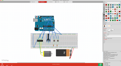
Fritzing Diagram:
Code used:
const int controlPin1 = 2;
const int controlPin2 = 3;
const int enablePin = 9;
const int directionSwitchPin = 4;
const int onOffSwitchStateSwitchPin = 5;
const int potPin = A0;
int onOffSwitchState = 0;
int previousOnOffSwitchState = 0;
int directionSwitchState = 0;
int previousDirectionSwitchState = 0;
int motorEnabled = 0;
int motorSpeed = 0;
int motorDirection = 1;
void setup(){
pinMode(directionSwitchPin, INPUT);
pinMode(onOffSwitchStateSwitchPin, INPUT);
pinMode(controlPin1, OUTPUT);
pinMode(controlPin2, OUTPUT);
pinMode(enablePin, OUTPUT);
digitalWrite(enablePin, OUTPUT);
}
void loop(){
onOffSwitchState =
digitalRead(onOffSwitchStateSwitchPin);
delay(1);
directionSwitchState =
digitalRead(directionSwitchPin);
motorSpeed = analogRead(potPin)/4;
if(onOffSwitchState != previousOnOffSwitchState){
if(onOffSwitchState == HIGH){
motorEnabled = !motorEnabled;
}
}
if (directionSwitchState !=
previousDirectionSwitchState){
if (directionSwitchState == HIGH){
motorDirection = !motorDirection;
}
}
if (motorDirection == 1){
digitalWrite(controlPin1, HIGH);
digitalWrite(controlPin2, LOW);
}
else {
digitalWrite(controlPin1, LOW);
digitalWrite(controlPin2, HIGH);
}
if (motorEnabled == 1){
analogWrite(enablePin, motorSpeed);
}
else{
analogWrite(enablePin, 0);
}
previousDirectionSwitchState =
directionSwitchState;
previousOnOffSwitchState = onOffSwitchState;
}
"Keep Moving"

Fritzing Diagram:

Code used:
const int controlPin1 = 2;
const int controlPin2 = 3;
const int enablePin = 9;
const int directionSwitchPin = 4;
const int onOffSwitchStateSwitchPin = 5;
const int potPin = A0;
int onOffSwitchState = 0;
int previousOnOffSwitchState = 0;
int directionSwitchState = 0;
int previousDirectionSwitchState = 0;
int motorEnabled = 0;
int motorSpeed = 0;
int motorDirection = 1;
void setup(){
pinMode(directionSwitchPin, INPUT);
pinMode(onOffSwitchStateSwitchPin, INPUT);
pinMode(controlPin1, OUTPUT);
pinMode(controlPin2, OUTPUT);
pinMode(enablePin, OUTPUT);
digitalWrite(enablePin, OUTPUT);
}
void loop(){
onOffSwitchState =
digitalRead(onOffSwitchStateSwitchPin);
delay(1);
directionSwitchState =
digitalRead(directionSwitchPin);
motorSpeed = analogRead(potPin)/4;
if(onOffSwitchState != previousOnOffSwitchState){
if(onOffSwitchState == HIGH){
motorEnabled = !motorEnabled;
}
}
if (directionSwitchState !=
previousDirectionSwitchState){
if (directionSwitchState == HIGH){
motorDirection = !motorDirection;
}
}
if (motorDirection == 1){
digitalWrite(controlPin1, HIGH);
digitalWrite(controlPin2, LOW);
}
else {
digitalWrite(controlPin1, LOW);
digitalWrite(controlPin2, HIGH);
}
if (motorEnabled == 1){
analogWrite(enablePin, motorSpeed);
}
else{
analogWrite(enablePin, 0);
}
previousDirectionSwitchState =
directionSwitchState;
previousOnOffSwitchState = onOffSwitchState;
}
Week 16 | Final Project Update 4/5
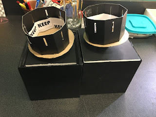
After assembling one of the zoetropes successfully, I'm now going to assemble the second one. I'm planning on using sturdy foam board as a cover. The boxes I made will hide the arduino and breadboard. Only the motor and whats assembled above will be seen.
Final_Project
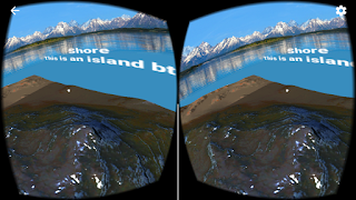
These are pictures and screenshots of the VR headset and apps I made in Unity. I used my iPhone 6S because its screen is bigger than my Samsung Galaxy S3 Mini.




Final_Project Diagram
Since I did not use the Arduino at all, I made a different diagram of my project:

-It shows the process of developing it, starting with the Google Cardboard SDK version 1.1.

-It shows the process of developing it, starting with the Google Cardboard SDK version 1.1.
Sunday, December 11, 2016
Final_Project[4] = MountainVR
-This is the last version
-I had a hard time to make the MainCamera see the Mountain. For some reason it was only seeing the skybox
-My original idea was to put the MainCamera above the highest mountain, so you can see the whole thing, but MainCamera would only see through the Mountain (and the entire GameObject).
Final_Project[3] = GazeInput
-This one took me a while to make it work.
-It is from a tutorial, but unfortunately, it used a very old version of the Google Cardboard SDK, so when I tried to use the scripts, Unity told me that they were deprecated and recommended to se the current versions.
-The ball was supposed to turn blue after 3 seconds of staring at it, but, again, with the current Google Cardboard SDK version, I had to add an Even Trigger System that only handles OnPointerEnter and OnPointerExit, even though GvrReticlePointer Script from the SDK has a OnPointerHover() function called every frame the user is still pointing at a valid GameObject, but I could not get it to work.
Final_Project[2] = MarsVR
-I found this really cool tutorial that explains how to create a skybox out of a panoramic view in Unity.
-I had to somehow tweak it because the Unity version used in the tutorial was an older one.
Final_Project[1] = Google Cardboard SDK
-This is something completely (and extremely) different from what I first wanted to do for the final project.
-My first idea was to just make a 2D game with the TFT screen like in the 2nd mini-project.
-I got a free VR Box (just paid shipping) so then I decided to make something with Virtual Reality
-The VR Box is similar to the Google Cardboard, but it does not have a physical Reticle or button that allows to perform screen touches. So I have to limit the mechanics to just staring at objects
-However, when testing it inside Unity, notice how I can do left click with the mouse when staring at the cube and it works fine.
-This is a scene that came with the Google Cardboard SDK for Unity (current version 1.1)
Thursday, December 8, 2016


Final Project: Demonstration
Final Project
I strayed from my original plan for my final project to be an abstract mirror. During my second mini-project critique, it was mentioned that it was like a windless wind chime, and that interested me. I decided to focus more on sound.
I wanted to subvert the relaxing nature of wind chimes, and to create an interactive thing that, the more someone interacted with it, the less they wanted to be around it. As a person got closer and spent more time around it, the motors would spin more violently and the sound of the chimes would evolve from soft and musical to more cacophonous. However, because my other motor couldn't spin the chimes, the sound never got that loud, and most people enjoyed it.

I strayed from my original plan for my final project to be an abstract mirror. During my second mini-project critique, it was mentioned that it was like a windless wind chime, and that interested me. I decided to focus more on sound.
I wanted to subvert the relaxing nature of wind chimes, and to create an interactive thing that, the more someone interacted with it, the less they wanted to be around it. As a person got closer and spent more time around it, the motors would spin more violently and the sound of the chimes would evolve from soft and musical to more cacophonous. However, because my other motor couldn't spin the chimes, the sound never got that loud, and most people enjoyed it.

Final Project: Structure
The structure ended up being the downfall of the larger motor; it wasn't strong enough to do what I wanted it to.
I wanted the small motor to spin things within other things that the larger motor would be spinning. That wasn't possible because cables would get tangled. So I made a wooden gear essentially that would be turned by the motor and would allow the smaller motor to turn in the center of it.

 Later a kind of tap was added to the edge of the wood to give the motor head better traction.
Both motors are mounted with two brackets and a cable tie.
The structure was then mounted onto trimmed 2x4s nailed to plywood.

Finally the hanging components and circuitry were added. It was at this point I learned my motor wasn't strong enough. I later stained the wood black.

I wanted the small motor to spin things within other things that the larger motor would be spinning. That wasn't possible because cables would get tangled. So I made a wooden gear essentially that would be turned by the motor and would allow the smaller motor to turn in the center of it.


Both motors are mounted with two brackets and a cable tie.
The structure was then mounted onto trimmed 2x4s nailed to plywood.

Finally the hanging components and circuitry were added. It was at this point I learned my motor wasn't strong enough. I later stained the wood black.

Final Project: Circuitry Completed + Schematic
I put a separate transistor for each motor; I wasn't sure if it was safe or even possible to run two motors through one transistor.
For my schematics, I couldn't actually find the TTL Jpeg Camera in the components menu, so I used something with four connections in its place, one for ground, power, TX(output, to pin 2), and RX(input, to pin 3). This ended up being some gas sensor.
I also couldn't find the exact rangefinder, so used another rangefinder with three connections in its place.


Demonstration for completed circuitry.
For my schematics, I couldn't actually find the TTL Jpeg Camera in the components menu, so I used something with four connections in its place, one for ground, power, TX(output, to pin 2), and RX(input, to pin 3). This ended up being some gas sensor.
I also couldn't find the exact rangefinder, so used another rangefinder with three connections in its place.


Final Project: Distance Sensor
The other input besides motion detection that I wanted was distance. I mapped the analog input of the sonar rangefinder to the speed of the motor so that the closer something was, the faster the motor went.
The rangefinder can sometimes seem a little unreliable. It will occasionally jump between huge values even though what it's looking at hasn't come any closer.
Demonstration
The smaller motor will be linked to the rangefinder, and the larger motor, to the motion detector.
The rangefinder can sometimes seem a little unreliable. It will occasionally jump between huge values even though what it's looking at hasn't come any closer.
Demonstration
The smaller motor will be linked to the rangefinder, and the larger motor, to the motion detector.
Final Project: Motion Detection
Motion detection played a big part in my last gesture, and I wanted to include it in my final as well. However, instead of it being "Motion detected = move, no motion = stay still," I wanted the motor linked to the motion detector to spin faster the longer it detected motion.
My code for it looks like this:
if (cam.motionDetected()) {
Serial.println("Motion!");
cam.setMotionDetect(false);
digitalWrite(motionLED, HIGH);
if (motorSpeed < 255) {
motorSpeed++;
}
delay(200);
cam.resumeVideo();
cam.setMotionDetect(true);
} else if (! cam.motionDetected()) {
Serial.println("Still.");
digitalWrite(motionLED, LOW);
//analogWrite(motionMotor, 0);
delay(200);
if (motorSpeed > 29) {
motorSpeed--;
}
if (motorSpeed == 30) {
motorSpeed = 0;
}
} else {
//analogWrite(motionMotor, 0);
//motorSpeed = 0;
}
Demonstration
The motionLED is the blue LED; I included it because sometimes the motion detector doesn't work; I can't quite figure out when it won't.
For each moment it detects motion, it increments speed by one:

My code for it looks like this:
if (cam.motionDetected()) {
Serial.println("Motion!");
cam.setMotionDetect(false);
digitalWrite(motionLED, HIGH);
if (motorSpeed < 255) {
motorSpeed++;
}
delay(200);
cam.resumeVideo();
cam.setMotionDetect(true);
} else if (! cam.motionDetected()) {
Serial.println("Still.");
digitalWrite(motionLED, LOW);
//analogWrite(motionMotor, 0);
delay(200);
if (motorSpeed > 29) {
motorSpeed--;
}
if (motorSpeed == 30) {
motorSpeed = 0;
}
} else {
//analogWrite(motionMotor, 0);
//motorSpeed = 0;
}
Demonstration
The motionLED is the blue LED; I included it because sometimes the motion detector doesn't work; I can't quite figure out when it won't.
For each moment it detects motion, it increments speed by one:

Wednesday, December 7, 2016
Final Project Process 5/5
Post Crit Thoughts:
The FSR worked to some extent. The piezo wasn't screeching like a hellbent banshee, so I'm marginally happy about that. The LEDs worked as anticipated. I only wish I had a pedestal for each of them to be situated on opposite sides of the room like a gallery space. Also, in a perfect world, I would have done as Juan suggested and connected the proximity sensor to a plant lamp so as to "give the plant life" with the attention you give it.
The FSR worked to some extent. The piezo wasn't screeching like a hellbent banshee, so I'm marginally happy about that. The LEDs worked as anticipated. I only wish I had a pedestal for each of them to be situated on opposite sides of the room like a gallery space. Also, in a perfect world, I would have done as Juan suggested and connected the proximity sensor to a plant lamp so as to "give the plant life" with the attention you give it.
Week 16 Final Project


int ledPin1=13;
int ledPin2=12;
int ledPin3=11;
int ledPin4=10;
int ledPin5=9;
int ledPin6=8;
int ledPin7=7;
int ledPin8=6;
int ledPin9=5;
int ledPin10=4;
int ledPin11=3;
int ledPin12=2;
int sensorPin=0;
float alpha=0.75;
int period=50;
float change=0.0;
void setup()
{
// Built-in arduino board pin
pinMode(ledPin1,OUTPUT);
pinMode(ledPin2,OUTPUT);
pinMode(ledPin3,OUTPUT);
pinMode(ledPin4,OUTPUT);
pinMode(ledPin5,OUTPUT);
pinMode(ledPin6,OUTPUT);
pinMode(ledPin7,OUTPUT);
pinMode(ledPin8,OUTPUT);
pinMode(ledPin9,OUTPUT);
pinMode(ledPin10,OUTPUT);
pinMode(ledPin11,OUTPUT);
pinMode(ledPin12,OUTPUT);
Serial.begin(9600);
Serial.print("Heartrate detection.\n");
delay(100);
}
float max =0.0;
void loop()
{
static float oldValue=1009;
static float oldChange=0.2;
// This is generic code provided with the board.
int rawValue=analogRead(sensorPin);
float value= alpha*oldValue +(1-alpha)* rawValue;
change=value-oldValue;
// Display data on the LED via a blip:
// Empirically, if we detect a peak as being X% from
// absolute max, we find the pulse even when amplitude
// varies on the low side.
// Reset max every time we find a new peak
if (change >= max) {
max= change;
Serial.println(" |");
digitalWrite(ledPin1,1);
digitalWrite(ledPin2,1);
digitalWrite(ledPin3,1);
digitalWrite(ledPin4,1);
digitalWrite(ledPin5,1);
digitalWrite(ledPin6,1);
digitalWrite(ledPin7,1);
digitalWrite(ledPin8,1);
digitalWrite(ledPin9,1);
digitalWrite(ledPin10,1);
digitalWrite(ledPin11,1);
digitalWrite(ledPin12,1);
} else {
Serial.println("|");
digitalWrite(ledPin1,0);
digitalWrite(ledPin2,0);
digitalWrite(ledPin3,0);
digitalWrite(ledPin4,0);
digitalWrite(ledPin5,0);
digitalWrite(ledPin6,0);
digitalWrite(ledPin7,0);
digitalWrite(ledPin8,0);
digitalWrite(ledPin9,0);
digitalWrite(ledPin10,0);
digitalWrite(ledPin11,0);
digitalWrite(ledPin12,0);
}
// Slowly decay max for when sensor is moved around
// but decay must be slower than time needed to hit
// next heartbeat peak.
max = max * 0.98;
// Display debug data on the console
// Serial.print(value);
// Serial.print(", ");
// Serial.print(change);
// Serial.print(", ");
// Serial.println(max);
oldValue=value;
oldChange=change;
delay(period);
}
Final Project Process 5/5
A proximity sensor turns on when the viewer is close to the box and then the viewer can see clearly what's inside. A mystery black box on a wall which contains my DCF (Florida Department of Children & Families) papers when I was in foster care. I decided to only use the significant ones such as in one in 1999 that my birthmother didn't show up to the visit. One in 2000 that the visit with my brother and birthmother went really well. Lastly, in 2001 when my adoption was finalized. In my experience as an adoptee, most people don't really know the foster system that well. Most people believe it's an orphanage of some-sort that the government runs which isn't true at all. The papers inside have a semi-gloss to them to represent self-identity and help the blue light bounce around inside the box. The blue light represents National Foster Care Month which is in May. It is symbolized with a blue ribbon.


const int signalPin= 0; //yellow wire connects to analog pin A0
const int LEDPin= 12; //LED connects to digital pin 13
int signal;//this variable, signal, will hold the analog value read by the arduino
void setup() {
Serial.begin(9600); //sets the baud rate for data transfer in bits/second
pinMode(signalPin, INPUT); //the infrared sensor signal line will be an input to the arduino
pinMode(LEDPin, OUTPUT); //the LED serves an output in the circuit
}
void loop() {
signal= analogRead(signalPin); //arduino reads the value from the infrared sensor
Serial.println(signal); //prints out analog value
delay(500); //delays the next analog reading by 500 ms or a half a second
if(signal > 199){ //if the analog value is less than 200, the object is within a few inches
digitalWrite(LEDPin, HIGH);
}
else{
digitalWrite(LEDPin, LOW);
}
}


Subscribe to:
Posts (Atom)